Send Message
Home ProductsPulse Jet Valve

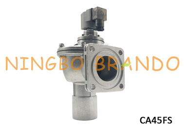
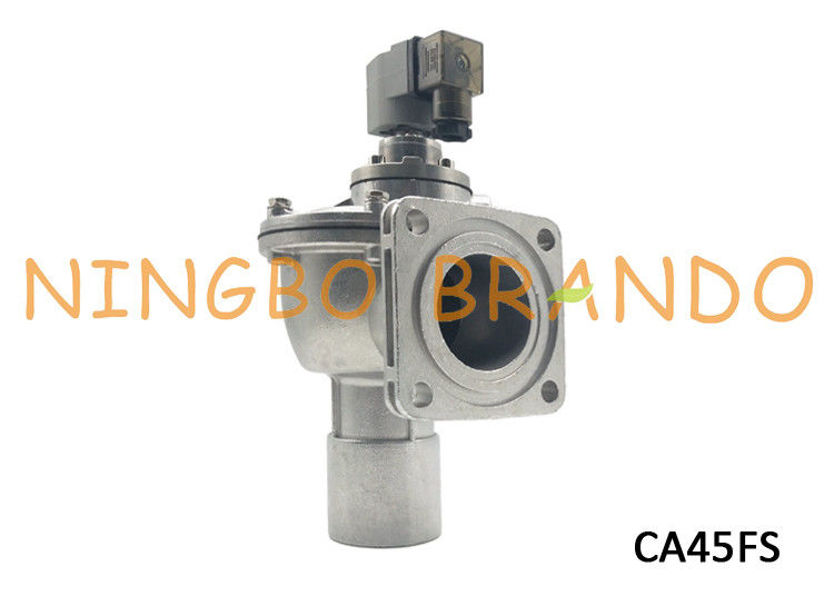
Goyen Type 2" Inlet 1-1/2" Outlet Flanged Pneumatic Pulse Valve for Dust Collector Systerm

Goyen Type 2" Inlet 1-1/2" Outlet Flanged Pneumatic Pulse Valve for Dust Collector Systerm

  • Goyen Type 2" Inlet 1-1/2" Outlet Flanged Pneumatic Pulse Valve for Dust Collector Systerm
  • Goyen Type 2" Inlet 1-1/2" Outlet Flanged Pneumatic Pulse Valve for Dust Collector Systerm
  • Goyen Type 2" Inlet 1-1/2" Outlet Flanged Pneumatic Pulse Valve for Dust Collector Systerm
  • Goyen Type 2" Inlet 1-1/2" Outlet Flanged Pneumatic Pulse Valve for Dust Collector Systerm
Goyen Type 2" Inlet 1-1/2" Outlet Flanged Pneumatic Pulse Valve for Dust Collector Systerm
Product Details:
Place of Origin: China
Brand Name: Brando
Certification: CE
Model Number: CA45FS
Payment & Shipping Terms:
Minimum Order Quantity: 1 pc
Packaging Details: inner boxes,cartons,pallets
Delivery Time: 7 working days
Payment Terms: L/C, T/T, Western Union
Supply Ability: 100000pcs per month
Contact Now
Detailed Product Description
Outlet Size: 1-1/2'' Outlet Inlet Size: 2''
Power: Solenoid Structure: Diaphragm
Working Medium: Air Working Pressure: 0.3~0.8Mpa
Working Temperature: -5℃~+55℃ Voltage: AC24V, AC110V, AC220V, DC24V
Temperature Of Media: AC220V, AC110V, AC24V, DC24V
High Light:

Goyen Pulse Valve

,

Goyen Diaphragm Valve

,

Goyen Solenoid Valve

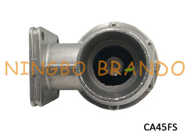
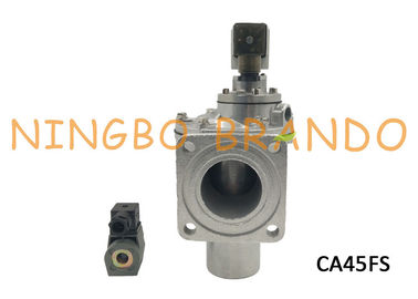
Goyen Type 2'' Inlet 1-1/2'' Outlet Flanged Pneumatic Pulse Valve for Dust Collector Systerm


Goyen Type Flanged dust collector pulse valve with diecast aluminum alloy body, wiedely used in baghouse . Baghouse are the most versatile dust collector style and can be used in all applications. Baghouse collectors with traditional bag filters are preferred for applications with larger or mixed range of dust particle sizes, heavier dust loading, fibrous/sticky dusts or higher temperatures (normally up to 550F, in some cases up to 750F with specialty fabrics).

The working principle :The high-pressure gas enters from the air inlet and enters the lower air chamber.
1. When the pulse valve is not powered, the gas enters the decompression chamber through the constant-pressure pipe on the upper and lower shells and the throttle hole therein. Because the valve plug blocks the pressure relief hole under the action of the spring, the gas will not be discharged. Make the pressure in the decompression chamber and the lower air chamber consistent, and under the action of the spring, the diaphragm will block the injection port, and the gas will not burst out.
2. When the pulse valve is energized, the valve core is lifted up by the electromagnetic force, the pressure relief hole is opened, and the gas is ejected. Due to the role of the orifice of the constant pressure pipe, the throughput of the pressure relief hole is greater than The flow velocity of the pressure pipe gas makes the pressure in the decompression chamber lower than the pressure in the lower chamber. The gas in the lower chamber lifts the diaphragm, opens the blowing port, and performs gas blowing.


Technical Data of CA45FS Flanged Valve:

Model No CA45FS
Port Size

1-1/2'' Outlet 2'' Inlet

Valve Type

Diaphragm Valve 

Action Type 

Pilot Operated 

Connection Type 

Flanged Inlet Port 

Temperature Range

-5℃~+55℃

Pressure  0.3~0.8Mpa
Body Material  Diecast Aluminum Alloy 
Seal Material  NBR(common, all available)
Voltage  AC24V, AC110V, AC220V, DC24V


Main Dimension of CA45FS double diaphragm pulse valve:

Main Dimension of CA45FS double diaphragm pulse valve:

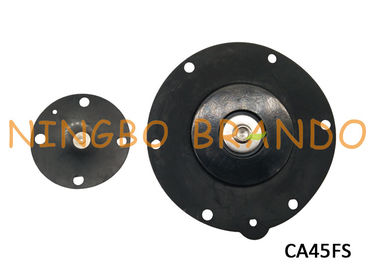
Details About CA45F​S Electromagentic Pulse Valve:

Details About CA45FS Electromagentic Pulse Valve:


Construction of CA45FS:

Body: Diecast aluminum
Ferrule: 305 SS
Armature: 430FR SS
Seals: Nirtrile or FKM
Spring: 304 SS
Screws: 302 or 304 SS
Outlet Slide Seal: EPDM or FKM
Diaphragm Seat: PA-66(standard). FKM coated mild steel


Connection Surface of CA45FS Diaphragm Pulse Valve:

Connection Surface of CA45FS Diaphragm Pulse Valve:


INSTALLATION of CA45FS AC220V AC110V AC24V DC24V Solenoid Pulse Valve:


1. Prepare inlet flanges and blowtube pipes to suit valve specification. Avoid installing valves underneath the tank.
2. Ensure tank and pipes are free from dirt, rust or other particulate.
3. Ensure supply air is clean and dry.
4. Mount valves to inlet flange and blowtube to valves with all seals in place. Tighten flange bolts to 10Nm (7.4 ft–lbs) Ensure blowtube is pushed all the way into the valve outlet.
5. Tanks and pipes must be independently supported from valve.
6. Make electrical connections to solenoid or connect RCA pilot port to pilot valve (RCA valves only).
7. Apply moderate pressure to system and check for installation leaks.
8. Fully pressurise system.
9. Test fire and listen for proper actuation and crisp pulse noise.Valve is not a structural component. Do not rely on valve to retain tanks or pipe. Where used, refer to product specification for installation details.


Welcome to your any question and inquiry!

Contact Details
Ningbo Brando Hardware Co., Ltd

Contact Person: Mia

Tel: +8613454729544

Send your inquiry directly to us
Best Products
Other Products