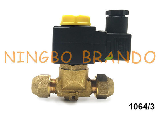
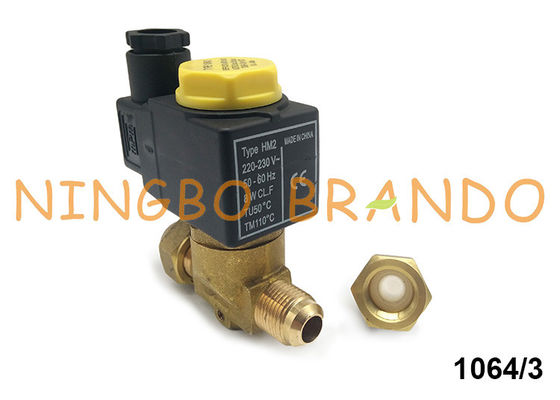
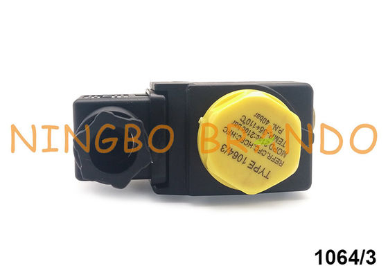
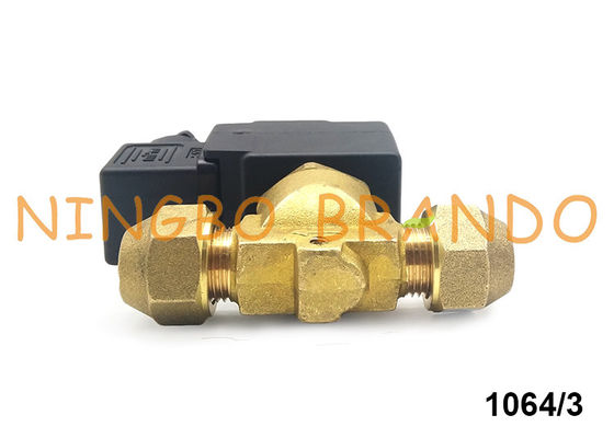
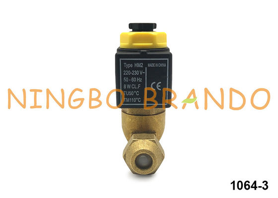
Castel Type SAE Flare 3/8'' Solenoid Valve 1064/3 For Refrigeration
Castel type solenoid valve is consist of Brass body, Stainless Steel plunger armature, coil and other parts.
The valve series 1034 ; 1038 ; 1040 ; 1048 ; 1049 ; 1050 ; 1058 ; 1059 ; 1078 (/11 , /13 , /M42) ; 1079 (/13 , /M42 , /17) ; 1098/9 ; 1099/11 are piston pilot-operated valves. Their operation depends not only on the magnetic field produced by the current flow into the coil, but also on a minimum inlet pressure, which is necessary to:
• open the piston and keep it lifted off the main opening
• close the piston and ensure the tightness on the main opening
Opening/closing of main valve seat is controlled by the piston, while opening/closing of pilot seat is controlled by the mobile plunger of the coil.
Fresh-keeping cabinet with 1064/3 MSV Series Diaphragm Pilot Solenoid Valve?
The structure of the rolling compressor of the fresh-keeping cabinet is mainly composed of a motor, a rolling piston, an eccentric shaft, a sliding piece, a spring, an air suction hole, an exhaust valve piece, etc. (no suction valve piece).
The slider of the fresh-keeping cabinet is equal in height to the cylindrical rotor, the cylinder height is slightly higher than the rotor, the cylinder head is covered with a cylinder head, and there is a certain gap between the piston end surface and the cylinder head plane, so that the piston and the slider can be freely in the cylinder. Movement, there are suction and exhaust holes on the cylinder block on both sides of the cylinder groove, the suction hole has no suction valve, and the refrigerant vapor directly enters the suction hole of the cylinder from the steam pipe. In order to prevent liquid blow, a gas-liquid separator is arranged on the suction pipe; an exhaust valve is arranged on the exhaust port, and the gas in the cylinder is discharged into the casing, so that the inside of the casing is a high-pressure gas zone, and then the high-pressure gas is further composed of a shell. The body enters the exhaust passage.
Fruit storage cabinet
The fresh-keeping cabinet rolling piston compressor is generally a vertical structure. The compressor is installed in the lower part of the fresh-keeping cabinet. The motor is in the upper part. The outer part of the whole cylinder is almost immersed in the lubricating oil. The cylindrical piston is installed in the cylinder and is placed on the eccentric shaft. Eccentric turn, eccentric axis. For the shaft to drive the piston in the cylinder along the cylinder wall surface of the cylinder wall has a through slot, the slot is equipped with a slider, the slider and the rotor fit in the slot sliding, under the action of the spring force and the rolling rotor outer wall surface The dynamic seal is formed by contact, and the crescent-shaped space between the rolling rotor and the cylinder wall is divided into a helium chamber and a compression chamber. During the process of rotating the eccentric shaft around the center of the cylinder, the helium chamber completes the intake process, and the compression chamber completes the compression. And the exhaust process.
Dimension:

|
Model
|
|
|
|
SAE (Flare), ODF (Solder)
|
|
|
|
|
|
|
1020/2
|
|
|
|
|
|
|
1020/3
|
|
|
|
1028/2
|
|
|
|
|
1028/3
|
|
|
|
|
1064/3
|
|
|
|
|
|
1064/4
|
|
|
|
1068/3
|
|
|
|
1068/4
|
|
|
|
1070/4
|
|
|
|
|
|
|
1070/5
|
|
|
|
1078/4
|
|
|
|
1078/5
|
|
|
|
1078/9
|
|
|
|
|
|
|
1078/11
|
|
|
|
|
|
|
1090/5
|
|
|
|
|
|
|
1090/6
|
|
|
|
|
|
|
1079/7
|
|
|
|
|
|
|
1079/11
|
|
|
|
|
|
|
1079/13
|
|
|
|
|
|
|
1098/7
|
|
|
|
|
|
|
1099/9
|
|
|
|
|
|
|
1099/11
|
|
|
|
|
|
Technical Data:
|
Operating Principles
|
Model Number
|
SAE Port
|
Seat size nominal Ø (mm)
|
|
|
TS(℃)
|
TA(℃)
|
|
min
|
max
|
min
|
max
|
|
Direct Acting
|
1020/2
|
1/4''
|
2, 5
|
0, 175
|
45
|
-35
|
+110
|
-35
|
+50
|
|
1020/3
|
3/8''
|
3
|
0, 23
|
|
Diaphragm Pilot Operated
|
1064/3
|
3/8''
|
6, 5
|
0, 80
|
45
|
-35
|
+105
|
-35
|
+50
|
|
1064/4
|
1/2''
|
|
1070/4
|
1/2''
|
12, 5
|
2, 20
|
|
1070/5
|
5/8''
|
2, 61
|
|
1090/5
|
5/8''
|
16, 5
|
3, 80
|
|
1090/6
|
3/4''
|
4, 80
|
|
Piston Pilot Operated
|
1034/3
|
3/8''
|
6, 5
|
1, 00
|
45
|
-35
|
+110
|
-35
|
+50
|
|
1034/4
|
1/2''
|
|
1040/4
|
1/2''
|
12, 5
|
2, 40
|
|
1040/5
|
5/8''
|
3, 00
|
|
1050/5
|
5/8''
|
16, 5
|
3, 80
|
|
1050/6
|
3/4''
|
4, 80
|
Installation:
Before connecting the valve to the pipe, it is advisable to make sure that the refrigerating system is clean. In fact, valves with P.T.F.E. gaskets, and particularly piston valves, are sensitive to dirt and debris. Furthermore, check that the flow direction in the pipe corresponds to the arrow stamped on the valve body. All the valves can be mounted in any position so long as the coil does not point downwards. The brazing of valves with solder connections should be carried out with care, using a low melting point filler material. It is not necessary to disassemble the valves before brazing, but it is important to avoid direct contact between the torch flame and the valve body, which could be damaged and compromise the proper functioning of
the valve.
Before connecting a valve to the electrical system, be sure that the line voltage and frequency correspond to the values marked on the coil.
Focus on your demands, Offer you best solution:
√ Contact us if some points you have doubt
√ Contact us if somewhere need to change
√ Contact us if not the one you are looking for
√ Contact us if you are doing designing
Welcome to your any question and inquiry!

 Your message must be between 20-3,000 characters!